flowchart TD
    A["I2C transaction"] --> B{"Configure GPIO pins<br>PA5 for SDA and PA6 for SCL"}
    B --> C["Enable Interrupts<br>TXIE, RXIE, STOPIE, NACKIE"]
    C --> D["Initialize Variables<br>Set up buffers"]
    D --> E{"Trigger transaction<br>write/read by setting CR2"}
    E --> F["Interrupt Handler:<br>TXIS Transmit Interrupt Status<br>RXNE Receive Not Empty<br>STOPF Stop Condition"]
    F --> G{"Update State variables"}
    G --> |"signal to new transaction"| E
MCU Design
Design Summary
The MCU (STM32L432KCU) interfaces with an MPU6050 sensor using I2C and sends processed data to an FPGA through SPI protocols. The main job purpose of the microcontroller is to read the gravity data, determine which side is down towards the earth, and convert it into a 360-degree angle with 0 degrees as the IMU facing the ceiling.
I2C and IMU Communication
The MPU6050 accelerometer operates in a ±2g range with a sampling rate of 1kHz. We configured a 400 kHz clock speed using GPIO pins PB6 (SCL) and PB7 (SDA). The REG_ACCEL_CONFIG register is configured for ±2g sensitivity and the REG_PWR_MGMT_1 register is cleared to enable the module. Data is read from the REG_ACCEL_XOUT_H register to capture X, Y, and Z-axis values.
We compute the tilt angle through trigonometric transformation: atan2(accel_x, accel_y) into a two-dimensional planar -180 to +180 degree angle and then map to the range of 0 to 360 degrees. Here ia a oscilloscope trace of a wake up call (write to device with address 0x68) of I2C: 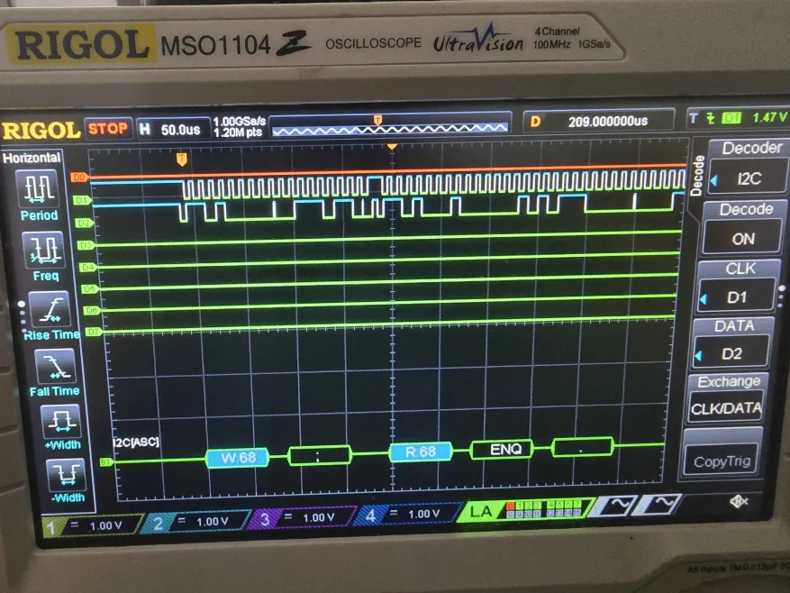
SPI Communication and Data Transfer
The MCU acts as the SPI sender and the FPGA is configured as the receiver for data. Our SPI is set up to be a one-way communication because we only require orientation data to let the physics engine on FPGA know as input while MCU alone doesn’t require any information from the FPGA. Our angular data rounded to integer is divided into high and low bytes for transmission. When chip select cs_n is detected high, we start to receive data and at every rising edge of sclk, a bit from sdi is shifted into the shift_reg. We have a bit_counter to increments to track the progress so that once it reaches 16, we can confirm that angle data is fully received. Here is a oscilloscope trace of a test SPI transmission: 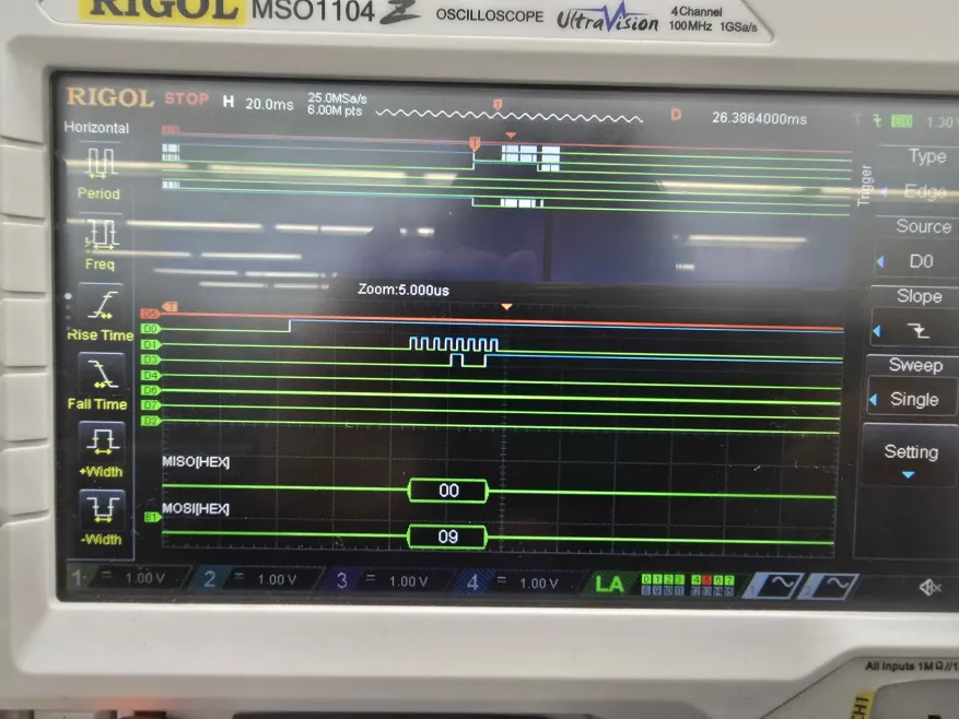
More information and specific implementation details can be found in our GitHub repository
Schematics
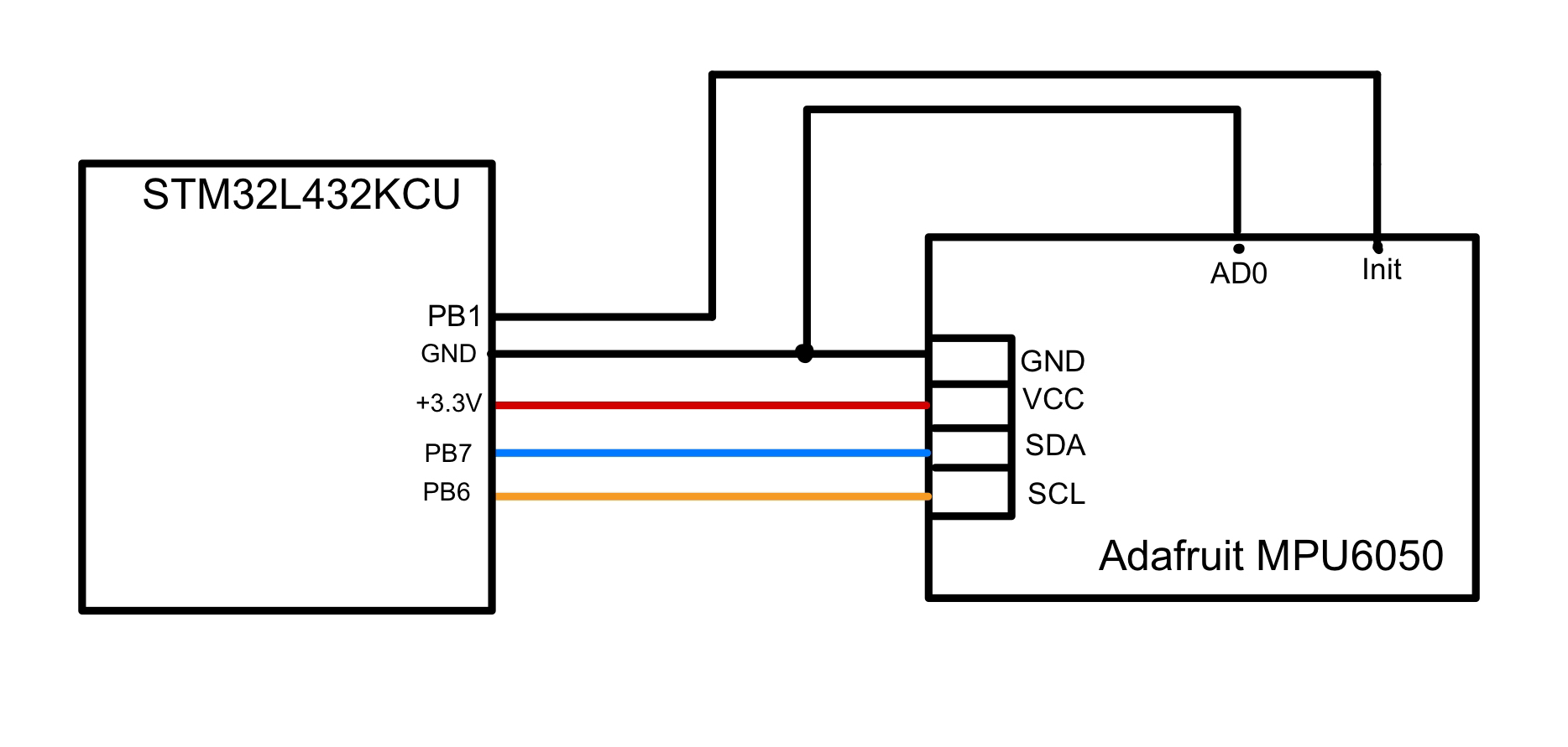
This is a schematic depicting the connection between the MCU and our MPU6050 accelerometer, which communicated over I2C.
Flowcharts
This flowchart displays the I2C Transaction Flow.
This flowchart displays the main program flow.
flowchart TD
    A["main"] --> B["Configure Flash and Clock,<br>Initialize Peripherals"]
    B --> C["Initialize I2C/SPI"]
    C --> D["Initialize MPU6050"]
    D --> E{"Check WHO_AM_I<br>verify 0x68"}
    E --> F["MPU6050 Data Reading<br>Parse MPU6050 Data"]
    F --> G["Calculate Angle<br>0-360 degrees"]
    G --> H["SPI Transmission to FPGA"]
    H --> I{"Delay 1s"}
    I --> |"loop back"| F