Results
Performance Achievements
We were able to meet all of the spec we set out for when we designed our final project.
- Display is responsive to user input in sub-second (<1 s) response time.
- Display driver is written to support full 12-bit color.
- Display driver refreshes at a maximum refresh rate of over 300 Hz with no ghosting and artifacts.
- Simulation updates with eight total directions of movement
- Simulation supports at least ten particles
- Simulation accounts for collisions of particles with each other and the border
- Simulation is fluid with no long term cumulative errors.
Design Decisions
FPGA Design Decisions:
We choose to use BCM to support a wider range of colors, as we felt like that would provide for a strong base in case we wanted to expand upon what we would like to do. We choose BCM instead of PWM, as BCM works by logarithmically dimming LEDs, which is much better suited for the human eye. We also only supported 12 bits of color, as oppposed to more, because that would decrease the refresh rate of our display, and we wanted an animation that was as smooth as possible, and thought that we did not need more colors.
One of the major issues we ran into on the FPGA side was getting our block rams to work properly in our physics engine. The original intention was to use our block rams for double buffering to calculate simulation results, but we were unable to get the timing working properly, which is why the simulation only supports so little particles, as they are all stored in LUTs and compared with one another.
MCU Design Decisions:
We choose to use I2C with interrupts ensures real-time responsiveness during live transactions by immediately handling events like data reception or transmission without delays, unlike polling which may miss fast-paced interactions. This design is crucial for our high-speed communication in time-sensitive display, ensuring minimal latency and accurate data handling.
SPI communication between MCU and FPGA is chosen for similar reason that it’s simple to implement and good for high-speed data transfer.
Overall:
We decided to put the physics engine in the FPGA. This allowed for faster simulations, which we thought would be especially useful if we wanted to develop our simulation into anything more complicated. We also weren’t sure how fast we wanted our simulation to refresh, and realized that SPI might not fully accommodate the bandwidth we needed to refresh our display very quickly.
Media
Here is the same video as on the homepage:
Build Process
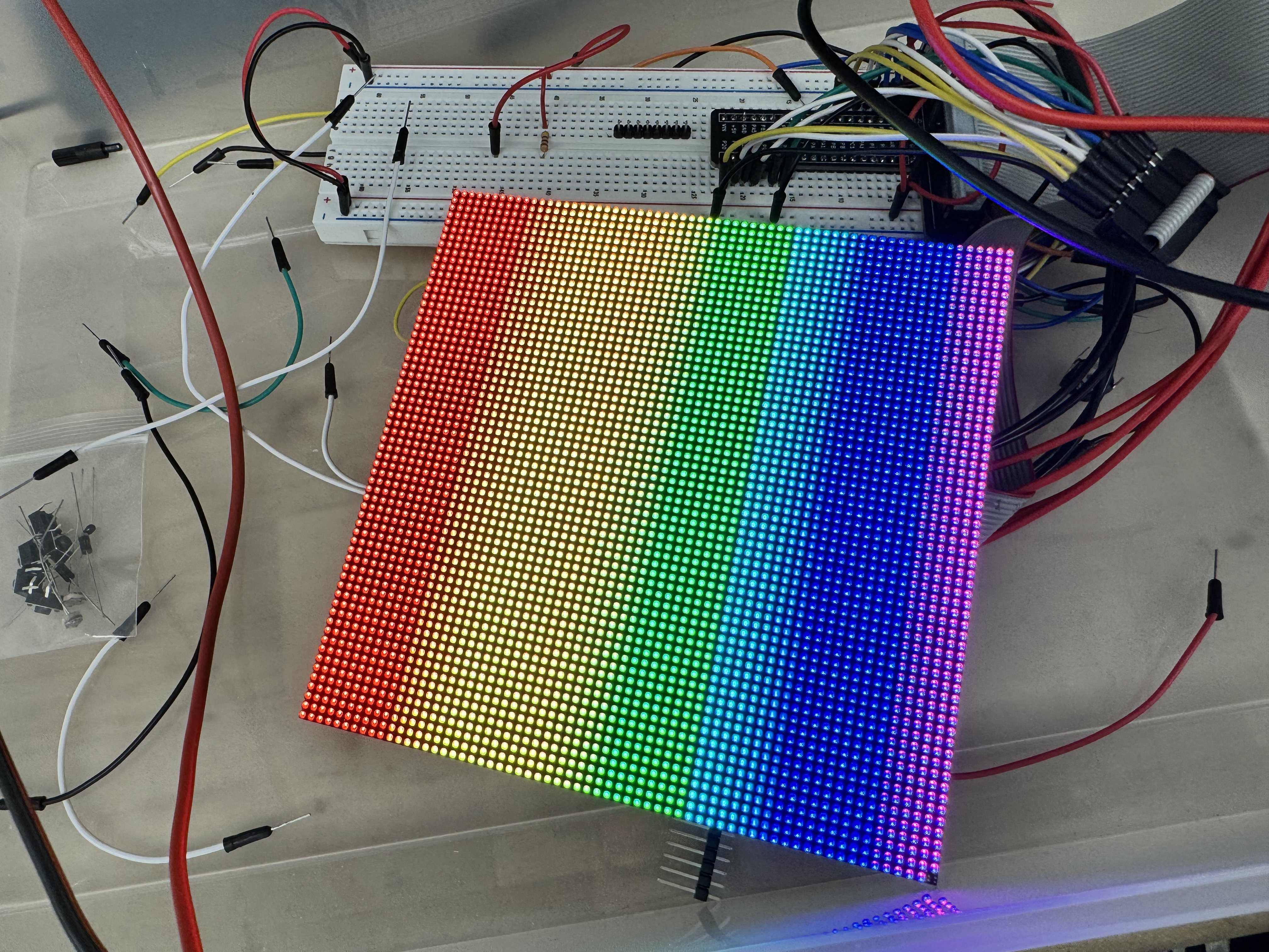
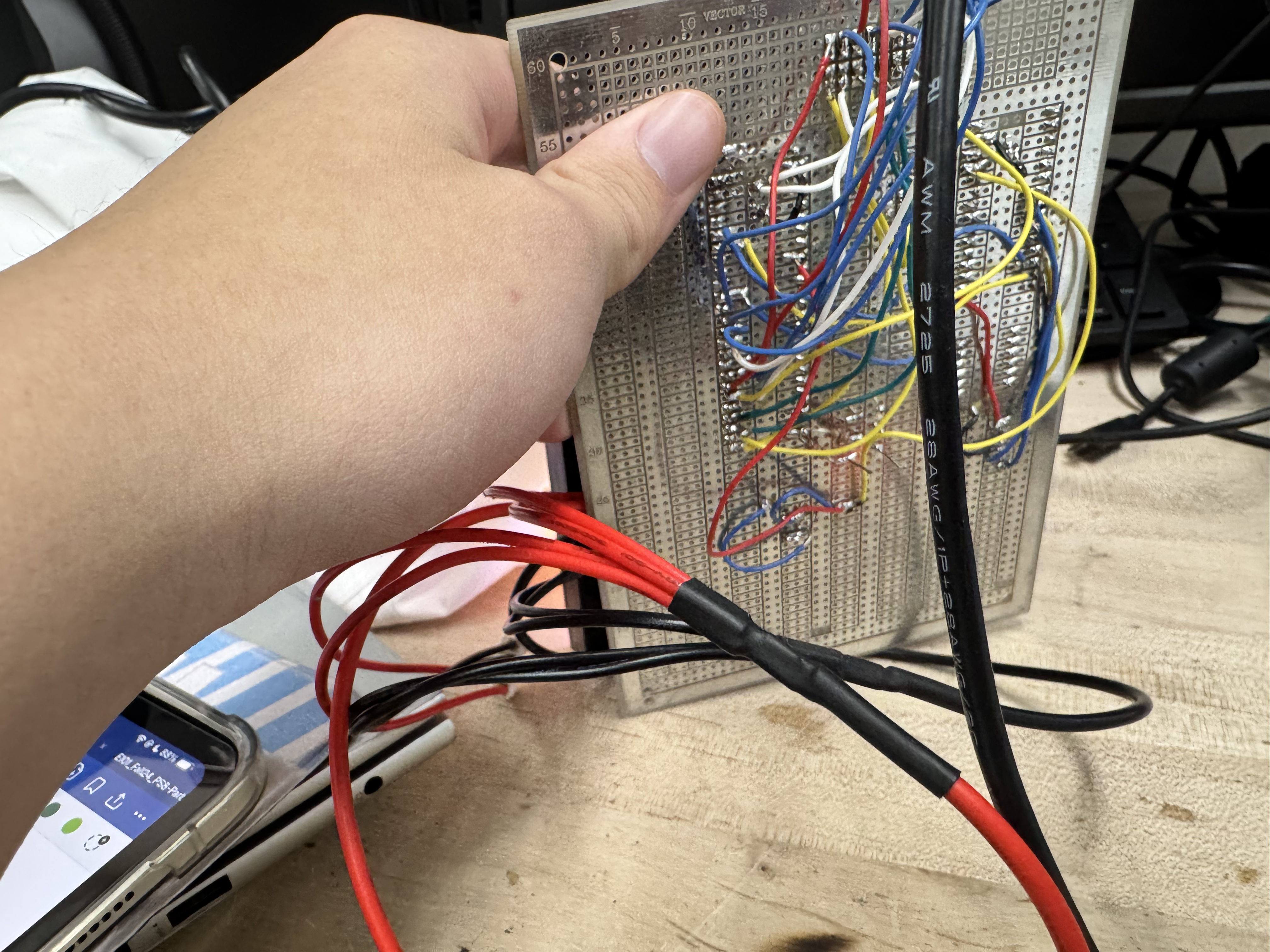
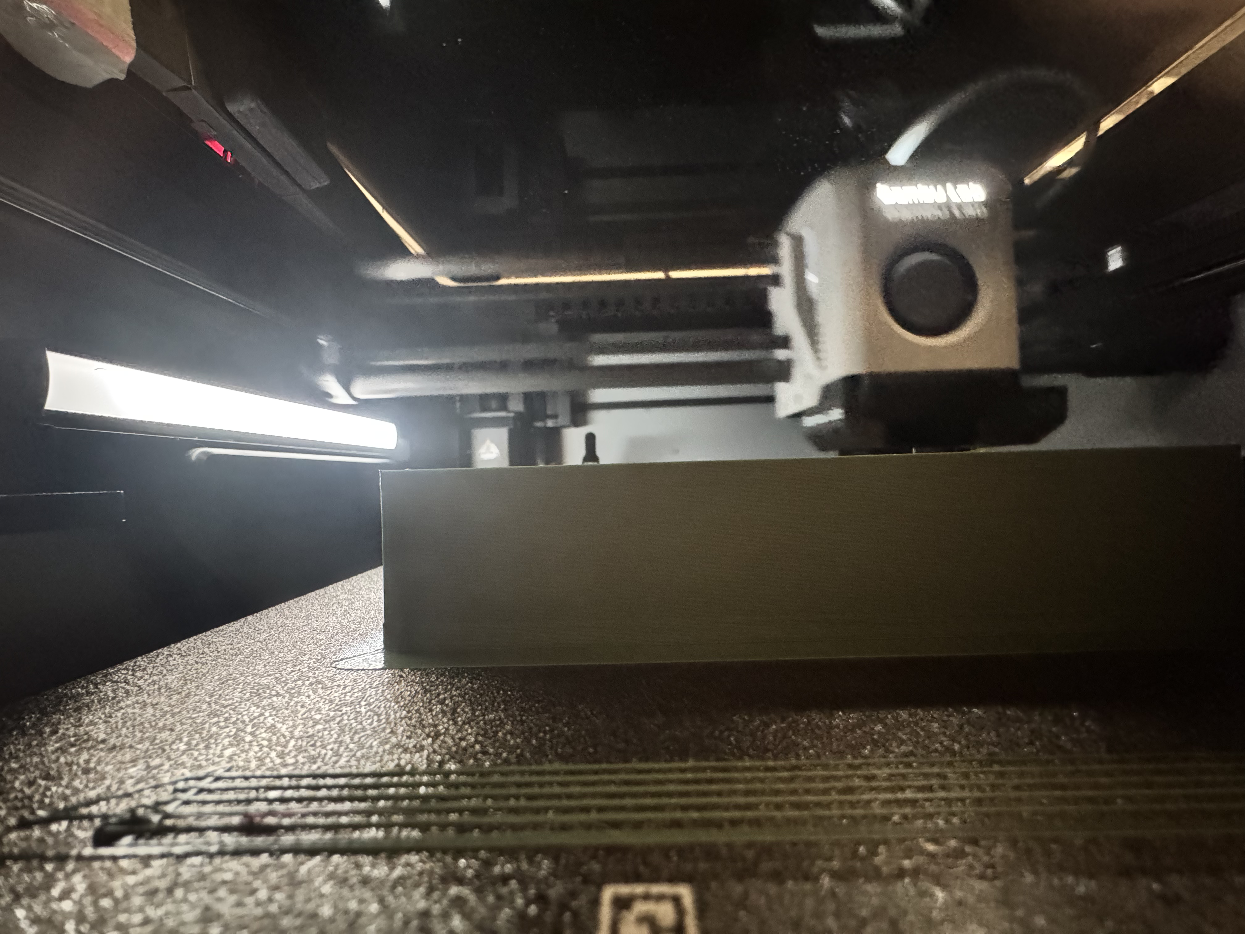
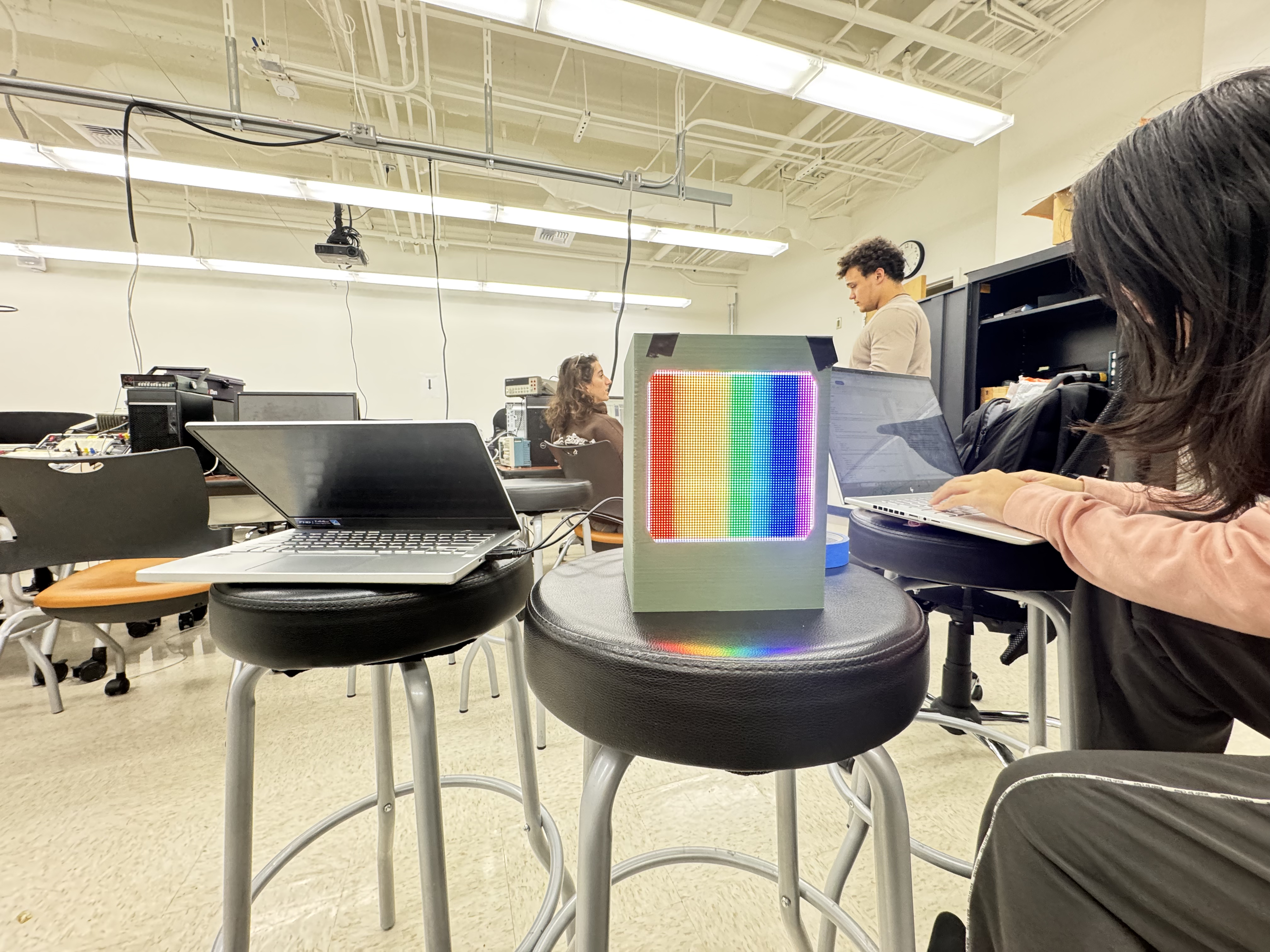
Here are some pics of the build process.
Simulation (Testbench) Output
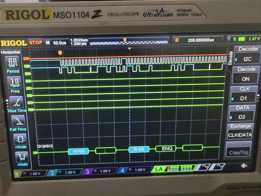
I2C Logic Analyzer
Here is a picture taken of our Oscilloscope/Logic Analyzer trace, analyzing the I2C and SPI traces between our MCU and our IMU.
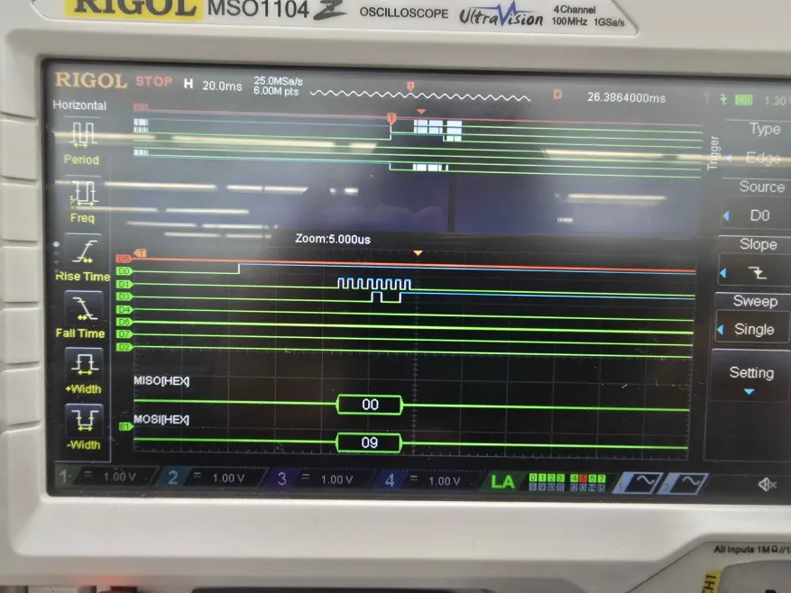
And here’s one for SPI to our FPGA.
Physics Engine Testbench
Below is a picture of a simulation created for our physics engine, to ensure that it’s outputting particles in the right place.


Future Work
MCU
If we wanted to expand the amount of inputs we were taking, we could also take use of more of the data coming from our IMU. This would allow us to do things like measure the relative acceleration, allowing us to implement even more things inside our simulation, as long as we get the associated FPGA side working.
FPGA
The biggest upgrade we would have to do is to properly support storing the particles in our simulation in Block RAM. This would allow us to have even more particles. From there on out, it would be feasible to support a variety of different particle behavior, and even build out games and the like in future iterations of this project.